

News
1. What Is a VFD Cable?
Improperly specified VFD cables are a leading hidden cause of unplanned industrial downtime, sporadic EMI tripping issues, and premature motor insulation failure. A Variable Frequency Drive (VFD) cable is a specialized industrial cable designed exclusively for direct VFD-to-motor connections. It is engineered to withstand high-frequency switching noise, rapid voltage transients, and reflected-wave overvoltage — extreme electrical stresses that standard motor cables cannot endure in variable-frequency operating systems.
VFD systems deliver precise speed and torque regulation for AC motors, bringing substantial energy savings and operational flexibility. They are widely deployed in industrial automation, manufacturing plants, water treatment facilities, commercial HVAC infrastructure, and various pump, fan, and conveyor-based equipment.
Unlike traditional motor circuits powered by stable, fixed-frequency sinusoidal power, VFDs operate through high-speed pulse-width modulation (PWM) switching. This core working mechanism generates sharp voltage spikes, high-frequency harmonics, and line capacitance effects, placing stringent requirements on cable insulation durability, EMI shielding performance, and symmetrical grounding design.
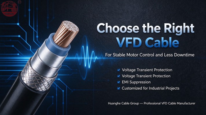
A properly matched VFD cable effectively suppresses high-frequency electromagnetic interference, protects motor and cable insulation from continuous electrical stress, and adapts to complex mechanical and environmental installation conditions. For industrial engineers and procurement professionals, cable selection should prioritize system electrical parameters, wiring distance, EMC compliance standards, and site operating conditions — rather than conductor size or upfront cost alone.
2. Why Is Choosing the Right VFD Cable Important?
Using generic motor cables or mismatched VFD cables in variable-frequency systems commonly leads to four critical operational issues: electromagnetic interference with nearby devices, cumulative insulation degradation, abnormal cable overheating, and accelerated cable aging. Standardized VFD cable selection ensures stable, low-maintenance, and long-term operation of VFD-driven motor systems.
Accurate VFD cable specification delivers tangible technical and commercial benefits for industrial projects, which are summarized as follows:
2.1 Electromagnetic Interference (EMI) Suppression
High-speed PWM switching in VFDs continuously generates high-frequency electrical noise. Without professional shielding, this EMI disrupts adjacent precision sensors, PLC control loops, communication wiring, and low-voltage instrumentation, causing signal drift, unexpected equipment tripping, and unstable automated production workflows. High-quality shielded VFD cables, paired with standardized shielding termination and compliant grounding practices, reliably isolate high-frequency noise and meet strict industrial EMC requirements.
2.2 Reduction of Insulation Electrical Stress
Rapid voltage transients generated by VFD switching subject cable and motor insulation to repetitive electrical stress. This stress intensifies with higher switching frequencies, longer wiring runs, and unfiltered VFD outputs, gradually deteriorating insulation performance and triggering partial discharge faults.
Nominal system voltage ratings (400V/480V) do not reflect actual pulse voltage levels in active VFD circuits. Only VFD-certified cables engineered to withstand high-frequency pulse operation can sustain long-term electrical stress and prevent sudden, catastrophic insulation breakdown.
2.3 Stable Heat Resistance & Operating Adaptability
Cable heat accumulation is affected by multiple site-specific factors, including motor operating current, ambient temperature, bundled cable density, installation methods, and continuous operating cycles. Professional VFD cables feature thermally optimized insulation and precision-sized conductors to avoid overheating under dynamic variable loads. Importantly, a cable’s voltage rating is independent of its current-carrying capacity and cannot be used for thermal sizing judgment.
2.4 Long-Term System Operational Reliability
Fully system-compatible VFD cables eliminate most cable-related system faults, reducing unplanned downtime and recurring maintenance costs. When combined with standardized installation practices, precise VFD parameter tuning, and routine equipment maintenance, proper cable specification greatly extends the service life of motors, drives, and the entire variable-speed system.
3. Key Factors to Consider When Choosing a VFD Cable
To avoid specification mismatches, on-site rework, and preventable operational risks, engineers and procurement teams must confirm the following core technical parameters before sending inquiries to VFD cable manufacturers.
3.1 Rated Voltage and Drive Compatibility
VFD cable voltage rating selection must match actual VFD output characteristics, rather than static nominal system voltage. Standard 400V and 480V industrial voltage grades are theoretical baseline values and do not account for pulse overvoltage and voltage reflection effects inherent to VFD operation.
Key verification criteria include motor rated voltage, VFD input and output switching parameters, VFD-specific pulse voltage grades, official manufacturer guidelines, actual field wiring length, and supplementary insulation protection requirements.
Industry Threshold Standard: For cable runs over 50 meters, reflected-wave overvoltage becomes highly prominent. Install dV/dt filters or sine wave filters per VFD manufacturer specifications to suppress terminal overvoltage and protect the entire insulation system.
Buyer Tip: Provide accurate motor voltage, complete VFD model number, and total wiring length during quotation requests to obtain fully customized, system-matched cable solutions.
3.2 Conductor Material: Copper or Aluminum
Copper conductors are the industry standard for heavy-duty and precision industrial VFD systems, offering superior electrical conductivity, stable heat dissipation, excellent oxidation resistance, and consistent current-carrying performance under dynamic variable-frequency loads.
Aluminum conductors feature lighter weight and lower upfront material costs, making them suitable only for low-load, weight-restricted industrial projects. They require larger cross-sectional areas and specialized aluminum-compatible terminals to prevent poor contact and overheating risks.
Comparison Copper Conductor Aluminum ConductorElectrical conductivity Higher for the same cross-sectional area Lower for the same cross-sectional areaConductor size Smaller conductor size meets electrical requirements Larger cross-sectional area required for equivalent performanceWeight Heavier LighterTermination Compatible with standard cable lugs and terminals Requires specialized terminals and professional pretreatmentSelection considerations Space limitation, electrical performance, long-term operational cost Weight limitation, installation space, terminal matching, initial installation cost
Final conductor material selection must comply with formal system electrical design and project specifications, rather than personal preference or cost-cutting considerations.
3.3 Conductor Cross-Sectional Area
Precise conductor sizing is essential for safe and reliable VFD motor operation. Undersized conductors cause excessive voltage drop and thermal overload, while unnecessarily oversized conductors increase material and installation costs without bringing additional operational benefits.
Professional cable sizing calculations cover multiple key variables: motor rated current, continuous operating duty cycle, total wiring length, allowable voltage drop, ambient working temperature, cable grouping density, conductor material type, and local electrical code requirements.
Most industrial three-phase VFD cables adopt a 3-phase + 1 protective earth core configuration. For example, a 4G6 mm² specification represents four total cores (including the green-yellow grounding core) with a 6mm² cross-section per core. Always verify official manufacturer datasheets for precise parameter confirmation.
Critical Rule: Never size VFD cables based solely on motor power ratings. Always cross-verify specifications against actual operating current, thermal working conditions, and official VFD manufacturer guidelines.
3.4 Insulation Material
VFD cable insulation must withstand continuous high-frequency electrical stress and repeated thermal cycling throughout its service life. Three mainstream industrial insulation materials serve distinct application scenarios:
XLPE (Cross-Linked Polyethylene): Features excellent thermal stability and pulse voltage resistance. Ideal for most fixed industrial VFD installations, delivering long-term aging resistance and stable electrical performance.
EPR (Ethylene Propylene Rubber): Offers outstanding flexibility and bending fatigue resistance. Perfect for dynamic applications such as drag chain systems, robotic arms, and repeatedly moving motor equipment.
PVC (Polyvinyl Chloride): A cost-effective general-purpose insulation solution, suitable only for low-stress, short-distance, fixed indoor VFD systems with minimal operational demands.
Important Note: Standard cables with the above insulation materials are not inherently VFD-rated. Always confirm that the cable is specially formulated to resist VFD-specific high-frequency pulse electrical stress.
3.5 Shielding Structure
Shielding performance directly determines a VFD cable’s EMC compliance capability, effectively controlling radiated and conducted electrical noise generated by high-speed VFD switching. Three professional shielding structures are widely used in industrial-grade VFD cables:
Copper wire braid shielding: Provides robust mechanical protection and low-resistance grounding paths. Its shielding efficiency depends on an industrial-standard braid coverage rate (≥85%) and standardized termination processing.
Metallic foil shielding: Provides 100% core coverage for superior high-frequency noise suppression, equipped with dedicated drain wires to ensure reliable static and noise current discharge.
Composite foil + braid shielding: Combines the full high-frequency noise coverage of metallic foil and the mechanical toughness of copper braid, meeting strict EMC Class A standards for high-precision industrial automation workshops.
High-performance shielding structures cannot deliver full functionality without standardized installation. Professional shielding termination, independent cable routing, and physical separation from weak signal cables are mandatory for stable and consistent EMI suppression.
3.6 Grounding and Protective Earth
Standardized symmetrical grounding is critical for VFD system safety and noise balance. All installation practices must strictly comply with official VFD manufacturer manuals and local electrical safety regulations.
Professional VFD cables are equipped with independent protective earth cores or symmetrical grounding structures to balance current distribution and reduce grounding impedance. Never use shielding layers as safety grounding conductors — this unsafe practice causes static accumulation, electric leakage, and complete shielding failure.
Confirm core configuration and grounding specifications during procurement to eliminate specification mismatches and avoid potential operational risks.
3.7 Outer Sheath and Environmental Resistance
The outer sheath protects the cable’s internal insulation, conductors, and shielding structure from mechanical damage and environmental deterioration. Sheath selection should match on-site conditions, covering oil and chemical resistance, waterproof and moisture-proof performance, outdoor UV stability, extreme temperature tolerance, abrasion resistance, bending flexibility, and flame retardancy.
Common industrial sheath materials include PVC, PE, and LSZH. Fixed static installations prioritize long-term aging resistance, while dynamic drag chain and moving equipment applications require high-flexibility, fatigue-resistant sheath materials. All environmental performance parameters should be verified through official manufacturer test reports and datasheets.
4. Shielded vs. Unshielded VFD Cables
Shielding configuration directly determines EMC compliance and overall system stability, with shielded and unshielded VFD cables serving completely different industrial application scenarios:
Feature Shielded VFD Cable Unshielded CableElectromagnetic compatibility Excellent EMI suppression, meets EMC Class A industrial standards No active noise shielding, requires strict routing isolationConstruction Integrated professional conductive shielding layer Basic structure without shielding designTermination requirement Standard shielding termination and bonding required Only standard protective earth connection neededApplicable scenarios Wiring over 50m, precision workshops, EMC-certified projects, high-interference environments Short-distance (<50m), isolated, low-noise ordinary industrial environmentsCost Moderate cost premium with full performance protection Cost-effective for basic low-demand applications
Most formal industrial VFD projects require shielded cables to meet mandatory EMC compliance standards. Always cross-check official VFD manuals and project technical specifications before finalizing cable selection.
Buyer Recommendation: When on-site environmental conditions or exact cable lengths are uncertain, prioritize shielded VFD cables to avoid post-installation electromagnetic interference problems.
5. How Does Cable Length Affect VFD Cable Selection?
Cable length is a critical yet easily overlooked factor in VFD system design. Longer wiring runs increase line capacitance and inductance, causing PWM voltage reflection and superposition at motor terminals and generating dangerous instantaneous overvoltage spikes.
Quantified Risks for Long-Distance Wiring (>50m): Aggravated insulation electrical stress, increased capacitive leakage current, amplified high-frequency EMI noise, and higher risk of motor winding breakdown.
There is no universal maximum wiring length applicable to all VFD systems. Allowable cable distances vary according to VFD switching frequency, internal cable structure, motor insulation grade, and filter configuration status.
For long-distance wiring projects, provide manufacturers with exact cable lengths and VFD operational parameters to confirm whether dV/dt filters, sine wave filters, or enhanced pulse-resistant VFD cables are required for system protection.
6. Common VFD Cable Applications
VFD cables support precise variable-speed motor control across all major industrial sectors, with performance characteristics tailored to unique application requirements:
6.1 Pumps and Water Treatment Systems
VFD-controlled pumps adjust water flow and pressure to achieve energy-efficient operation. Cables for water treatment applications require excellent waterproof, moisture-proof, and corrosion-resistant properties to adapt to humid underground and outdoor field environments.
6.2 HVAC Systems
VFD-driven fans and circulation pumps are core energy-saving components for modern commercial and residential buildings. Corresponding VFD cables must comply with building electrical codes, deliver low EMI output, and maintain stable performance for long-term fixed indoor installation.
6.3 Manufacturing and Automation
Conveyors, compressors, and automated production lines operate in complex high-interference factory environments, requiring VFD cables with superior mechanical abrasion resistance, bending fatigue resistance, and reliable EMI shielding performance.
6.4 Industrial Processing Plants
Chemical processing, food manufacturing, and pharmaceutical facilities involve persistent oil contamination, chemical corrosion, and high-temperature operating conditions, requiring customized oil-proof, acid-alkali resistant, and thermally stable VFD cables.
6.5 Renewable Energy and Auxiliary Equipment
Wind and solar power auxiliary variable-speed motor systems rely entirely on professional VFD cables. Standard power cables cannot replace dedicated VFD cables due to their inability to withstand high-frequency pulse electrical stress.
7. Common Mistakes to Avoid When Buying VFD Cables
Most VFD system operational failures result from avoidable procurement and specification errors. The six most common and costly mistakes are summarized below for engineering and procurement teams:
7.1 Choosing Only by Price
Low-cost generic alternative cables often compromise on insulation thickness, shielding coverage density, conductor cross-sectional area, and environmental resistance. Always compare supplier quotations based on identical technical specifications rather than unit price alone.
7.2 Replacing VFD Cables with Ordinary Shielded Cables
General shielded power cables lack VFD-specific pulse-resistant insulation and professional EMC structural design. They cannot withstand repetitive high-frequency voltage stress during VFD operation and will degrade rapidly in variable-frequency systems.
7.3 Ignoring Long-Distance Wiring Effects
Short-distance VFD cable selection standards do not apply to wiring runs exceeding 50 meters. Long-distance projects require dedicated overvoltage suppression and EMI mitigation measures to ensure system stability.
7.4 Neglecting Standardized Grounding Rules
Unclear core configuration and non-standard grounding construction easily lead to shielding failure and electric leakage risks. Confirm complete grounding design and termination protocols before production and on-site installation.
7.5 Disregarding Environmental Adaptability
Indoor fixed-installation cables degrade rapidly in outdoor UV-exposed, corrosive, or dynamic bending scenarios. Always match sheath performance parameters to actual on-site operating conditions.
7.6 Assuming All Industry Standards Are Equivalent
General power cable industry standards do not cover VFD-specific high-frequency electrical performance and EMC compliance requirements. Verify project-specific certifications and testing standards independently during procurement.
8. VFD Cable Procurement Checklist
Use this complete parameter checklist before submitting supplier inquiries to eliminate specification mismatches and ensure accurate, compliant manufacturer quotations:
Item Information to ConfirmApplication Pump, fan, conveyor, compressor, or other motor-driven equipmentDrive and motor VFD model, motor power rating, system working voltageCable length Exact distance between VFD and motor equipmentConductor Copper or aluminum conductor materialCable size Conductor cross-sectional area and core quantity specificationInsulation Insulation material and voltage resistance gradeShielding Copper braid, foil, or composite shielding structureGrounding Protective earth core configuration and special grounding requirementsOuter sheath Oil, UV, moisture, chemical, and abrasion resistance requirementsInstallation Fixed/outdoor/tray/conduit/dynamic bending applicationStandards Applicable industry standards and project customized specificationsQuantity & Delivery Total length, packaging standard, delivery cycle and scheduleDocumentation Datasheet, test reports, certification and inspection documentsDelivery terms Destination and Incoterms (EXW, FOB, CIF, etc.)
If complete technical specifications are unavailable, share existing cable datasheets and equipment manuals for professional manufacturer technical evaluation. Full parameter confirmation eliminates supply mismatches and costly on-site rework.
9. How to Evaluate a VFD Cable Manufacturer
In industrial project procurement, product reliability and professional technical support take priority over low unit prices. Qualified VFD cable manufacturers must meet the following core qualification criteria:
Technical conformity: Capable of customizing cable structures (insulation, shielding, grounding, outer sheath) to fully match project-specific electrical and environmental requirements.
Complete certification documentation: Able to provide standardized datasheets, third-party performance test reports, and industry compliance certificates to support project inspection and acceptance.
Professional production capability: Specializes in manufacturing industrial-grade customized VFD cables for long-distance wiring, dynamic bending, outdoor corrosion resistance, and high-EMI industrial environments.
Strict quality control: Implements full-process production testing and quality inspection to ensure consistent product performance and long-term operational reliability.
Transparent commercial terms: Provides clear quotation validity, MOQ rules, production lead times, packaging standards, and delivery terms to avoid transaction disputes.
Professional technical service: Proactively identifies potential specification risks and provides optimized VFD cable solutions for complex industrial projects.
10. Frequently Asked Questions About VFD Cables
10.1 What is the difference between a VFD cable and a regular motor cable?
VFD cables feature pulse-resistant insulation, professional EMI shielding, and symmetrical grounding structures specially optimized for VFD PWM switching, voltage reflection, and high-frequency noise suppression. Standard motor cables are designed only for fixed-frequency sinusoidal power. They cannot withstand repetitive electrical stress in VFD systems, leading to premature insulation aging, continuous EMI interference, and irreversible motor damage.
10.2 Does every VFD cable need shielding?
Shielding is not mandatory for all VFD cables. Shielded VFD cables are required for wiring runs over 50 meters, EMC-regulated projects, and high-interference industrial workshops. Short-distance, isolated, low-noise indoor environments can adopt certified unshielded VFD cables to control project costs while maintaining stable system operation.
10.3 Which conductor material is suitable for a VFD cable?
Copper is the preferred conductor material for most industrial VFD projects, offering high electrical conductivity, stable heat dissipation, and long-term operational reliability. Aluminum conductors are only suitable for low-load, weight-limited projects and require oversized cross-sections and specialized terminals to prevent connection overheating.
10.4 Can a VFD cable be installed outdoors?
Standard indoor VFD cables are not suitable for outdoor exposure. Outdoor installations require UV-stabilized, waterproof, and weather-resistant VFD cables to prevent sheath cracking, insulation aging, and performance degradation caused by sunlight, rain, and temperature fluctuations.
10.5 How do I determine the correct VFD cable size?
Never size VFD cables based solely on motor power ratings. Calculate cable size according to motor continuous operating current, total cable length, allowable voltage drop, ambient temperature, cable grouping density, and conductor material, then verify results against local electrical codes and official VFD manufacturer guidelines.
10.6 What information should I provide when requesting a VFD cable quotation?
To obtain accurate and compliant quotations, provide suppliers with system voltage, motor power/current, exact cable length, conductor type and size, core configuration, insulation/shielding/grounding requirements, sheath environmental resistance standards, applicable industry specifications, purchase quantity, and delivery terms. Attaching the official VFD model and manufacturer recommendations further improves solution accuracy.
Conclusion
Scientific VFD cable selection eliminates hidden equipment faults, reduces unplanned industrial downtime, and extends the service life of variable-speed motor systems. All core technical parameters — voltage compatibility, conductor sizing, insulation grade, shielding structure, grounding design, cable length adaptability, and environmental resistance — require comprehensive evaluation during system design and procurement.
The optimal VFD cable solution is neither the lowest-cost nor over-specified option, but the one that perfectly matches a project’s electrical, mechanical, environmental, and regulatory requirements. Complete and clear technical specifications enable manufacturers to deliver accurate, compliant quotations and avoid costly cable selection errors.
Looking for a reliable industrial VFD cable manufacturer for your upcoming project?
Share your full technical specifications, required quantity, and delivery timeline with Huanghe Cable Group’s expert team. Our professional engineers will evaluate your on-site project conditions and provide customized, cost-effective, EMC-compliant VFD cable solutions tailored to your needs.
Submit your VFD cable specifications today to get an accurate factory quotation.